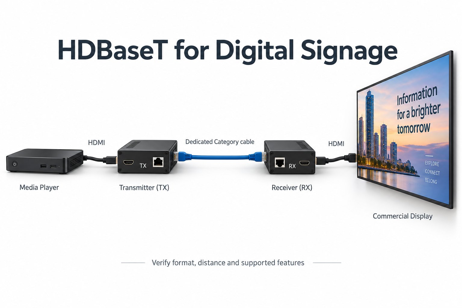
What should an HDBaseT signage link include?
Plan the source, transmitter, dedicated Category-cable link, receiver and display as one supported system. HDBaseT should not be assumed to pass through an ordinary Ethernet switch.
- Confirm the exact transmitter and receiver support the required format and distance together.
- Include cable construction, patch leads, terminations and wall plates in the specification.
- Confirm power and control functions separately.
- Test EDID, protected content, playback and recovery through the finished route.
The connector shape does not tell you how the link works. An HDBaseT socket and an Ethernet socket can look similar while serving different purposes. Before ordering, define the required video format, route, control functions and power arrangement. Then check the specific transmitter and receiver as a pair.
Draw the complete connection first
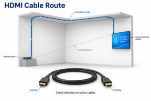
Start with a simple drawing: source, transmitter, installed cable, receiver and display input. Add every adapter, wall plate and patch lead that will remain in the finished installation. A connection that works with a short bench cable still needs testing through the actual route.
Identify which device creates the content and which device displays it. A network-connected signage player may download material over Ethernet, then send video through HDMI and an HDBaseT extender. Those are separate parts of the system. The network connection does not make the extender a network video decoder.
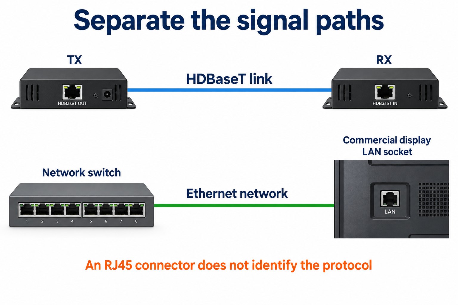
Some commercial displays have a compatible receiver built in. Others require an external receiver. Read the input specification for the exact display model. A LAN socket is not evidence of an integrated HDBaseT input, and an HDMI input does not establish that a receiver is included.
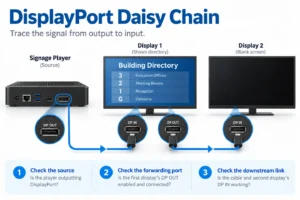
For several screens, draw each branch and its destination. Do not assume that a single transmitter can be split with ordinary network hardware. A distribution amplifier, matrix or network video system must be chosen for the intended architecture and documented as part of the design.
What an HDBaseT specification does and does not promise
The HDBaseT Alliance technology overview describes different generations and feature sets. Supported video, distance and auxiliary functions depend on the implementation. A headline distance or a version number is therefore only a starting point for checking a particular extender pair.
For example, the Alliance describes HDBaseT 3.0 support for uncompressed 4K at 60 Hz with 4:4:4 chroma over up to 100 meters under its specified cable conditions. That does not mean every product bearing the HDBaseT name supports that combination. Read the manufacturer’s format-and-distance table.
Turn the project requirement into a complete signal description. Include resolution, frame rate, chroma format and color depth, plus audio if needed. “4K support” alone leaves too much unanswered. The source, extender pair and display must all support the combination you intend to use.
For menu boards and directories, inspect small text as well as photographs. A video demonstration may look acceptable while fine colored lettering reveals a format limitation. Keep the chosen output format in the commissioning record so a later player update does not silently change the test conditions.
Keep HDBaseT separate from Ethernet switching
A normal Ethernet switch is not a substitute for an HDBaseT distribution device. The Alliance’s control and connectivity guidance explains that an HDBaseT link cannot simply pass through an Ethernet switch. Some equipment can carry an Ethernet channel alongside other functions, but its connections must follow the product documentation.
Label both ends of the installed cable with the destination and signal type. In a busy cabinet, a familiar RJ45 connector can invite an incorrect patch. Use a connection schedule that distinguishes the display’s LAN connection from the dedicated video extension path.
If the project needs video routed across an existing network, evaluate a suitable AV-over-IP system as a separate design. Confirm switching, bandwidth and management requirements with that system’s supplier. Do not assume that an HDBaseT transmitter can join it merely because both use Category cabling.
Choose a transmitter and receiver together
Ask for written confirmation of compatibility between the exact models. Start with the intended video format and installed distance, then check the auxiliary functions one by one. A working picture does not prove that USB, serial control, audio return or remote power will also behave as required.
For a mixed-brand proposal, request a tested combination or arrange a sample test before the final installation. Retain model numbers and firmware versions. If one unit is replaced during maintenance, compare the replacement’s documented capabilities rather than relying on a similar front panel or product name.
Record the direction of each function. Video normally travels from the player toward the display, but control or return channels may have different arrangements. A touch kiosk, for example, can require touch data to travel back toward the computer. That requirement needs an explicit supported path.
For interactive kiosk projects, verify the touch interface separately from the video connection. Check the controller, operating system and complete extension arrangement with the actual application. A successful video demonstration is not a substitute for a working touch session.
Plan cable, terminations and the installed route
Use the cable construction and Category rating specified for the selected equipment and target format. Read any restrictions on shielding, patch leads, connectors and total channel length. A cable with a familiar category label is not, by itself, proof that the complete installed channel meets the requirement.
Measure the route that the installer will actually use. Include rises, service loops and patching between rooms or cabinets. Mark the proposed termination points on the drawing. The straight-line distance between player and display is useful for a sketch, but it is not the installed cable length.
Ask the installer to document the cable type and termination method. Keep cable test results with the project file where such testing is specified. Follow the equipment and cabling manufacturers’ installation instructions, including bend-radius and separation requirements, rather than improvising a universal rule for every site.
Arrange access to both endpoints. A receiver hidden behind a permanently closed display may be difficult to inspect or replace. Check space for connectors, ventilation and service access before approving the mounting detail. The extension equipment should not obstruct the display’s own required clearances.
Specify power and control rather than assuming them
List where each endpoint receives power and which approved supply is used. Some products support power delivery across the link; others need a supply at each end. Confirm the exact supported arrangement. Do not connect equipment on the assumption that every remote-power system is interchangeable.
Distinguish powering the receiver from powering the commercial display. Even if the receiver can operate without a local adapter, the screen may still need its own mains connection. Put both requirements on the installation drawing so the electrical plan matches the equipment list.
For scheduled power control, identify whether the system uses serial commands, an infrared path, HDMI CEC or a network interface. Verify the required control function at both endpoints. Read the display’s command documentation and test the sequence with the actual controller before relying on it for unattended operation.
Include a restart test. Observe what happens when the player starts before the display, then repeat with the order reversed. Record whether the expected picture and control connection return without manual intervention. This is a project acceptance check, not a claim that every extender handles startup identically.
Check EDID and protected content through the whole chain
Ask how the transmitter handles display identification information and whether any fixed output or stored EDID mode is being used. Record the chosen setting and the reason for it. A setting that produces a picture on the bench may not be appropriate after the display or source changes.
Use the intended player and content during acceptance. If the project uses protected sources, verify their requirements across the entire connection. Do not treat a successful unprotected test image as proof that all subscription or protected content will work through the same chain.
When a picture disappears, change one variable at a time. First establish a direct, known-good source-to-display connection. Then introduce the transmitter and receiver with the supplier’s recommended test cable. Finally test the installed route. This sequence helps separate source configuration, endpoint compatibility and cabling problems.
Keep a record of symptoms instead of describing every fault as “no signal.” Note whether the link indicator changes, whether audio continues and whether the issue follows a particular output format. Provide those observations to the equipment supplier along with model and firmware details.
A commissioning plan for a signage installation
Establish a baseline
Prepare a small set of representative content: a menu or directory with fine text, a still image, and a video file if video is part of the project. Confirm the source’s actual output settings. Save the files and settings so the same baseline can be used after installation or maintenance.
Connect the approved endpoints on the bench and record a working configuration. Check video, required audio and every specified control channel. Do not leave optional functions untested if the project depends on them. Resolve uncertain compatibility before the equipment is installed in an inaccessible position.
Test the final route
Repeat the baseline through the installed cabling, including the patch leads and wall plates that will remain in service. Run the display in its intended operating mode. Follow the supplier’s guidance for test duration and thermal conditions rather than claiming that a brief picture check proves long-term reliability.
Inspect the actual content from normal audience positions. Check that the image is not cropped, stretched or unexpectedly reduced in quality. Confirm that the display selects the intended input after a restart. If a controller changes inputs or power state, exercise the complete sequence.
Make the handover repeatable
Give the maintenance team a connection drawing, endpoint models, firmware details and the approved source format. Include the cable labels and power locations. Keep a short recovery procedure that identifies which devices may be restarted and which settings must be preserved.
List the conditions that require a new compatibility check: a replacement player, a different receiver, a new display input or a higher-bandwidth output format. A stable installation should not be changed casually because another setting is available in a menu. Verify the revised configuration before rolling it out.
Questions to ask before placing an order
Request a single answer sheet for the proposed combination. It should identify the transmitter, receiver, cable requirement, supported format at the proposed distance and required power supplies. Add the control functions and the display input. Ask the supplier to mark unsupported or untested features clearly.
For repeat installations, keep the approved equipment list tied to a drawing revision. If procurement proposes a substitute, review the change against the same acceptance sheet. This is more useful than approving a substitute solely because its packaging says HDBaseT or advertises the same maximum distance.
Consider whether a local signage player would simplify the project. An extended connection can be useful when equipment must remain in a central location. If content can be managed locally or over the network, compare the service access and operational requirements of that arrangement as well.
Common HDBaseT questions
Can I plug the transmitter into the display’s LAN port?
Only use the connection specified by the display manufacturer. A LAN port normally serves networking, while an HDBaseT input must be explicitly identified. If the display has no compatible integrated receiver, the proposed design may require an external receiver connected to a supported video input.
Does every HDBaseT extender reach the same distance?
No. Check the product’s format-and-distance table and cable conditions. Distance claims may differ with signal format and equipment generation. Evaluate the complete installed channel and the exact video mode instead of applying a headline maximum to every combination.
Will an extender improve picture quality?
Its purpose is to transport a supported signal between locations. It does not turn unsuitable artwork into readable content or correct the display’s optical limitations. Confirm that the required format reaches the screen correctly, then assess brightness, text size and viewing conditions separately.
Do YJCEN displays include HDBaseT?
Do not assume that they do. Confirm the inputs and any required receiver for the exact product configuration. For a project using commercial wall-mounted signage, provide the proposed signal-chain drawing when requesting a quotation.
Review the complete display connection
Send the intended content format, cable route, control needs and proposed endpoints to YJCEN’s team. We can discuss the display configuration and the checks to carry out with the integration equipment supplier. Final compatibility should be confirmed against the selected hardware and an approved sample test.