How long can an HDMI cable run for digital signage?
There is no single distance that works for every cable and signal. Specify the actual route, required format and complete equipment path, then test that combination.
- Measure the cable route, including cabinet access and the final drop.
- Confirm the selected cable or extension method at the intended resolution and timing.
- Include adapters, wall plates, direction and power requirements in the test.
- Establish a known-good short connection, then test the full link before and after installation.
For a lobby, restaurant or retail installation, the practical question is whether the selected connection reliably carries the required picture and control functions through the planned path. This guide explains what to measure, what to ask the cable supplier and how to test the route before handover.
There is no single maximum distance for every HDMI cable
HDMI Licensing Administrator states that the Ultra High Speed HDMI cable specification does not set one cable length; construction and cable type affect the available length. Avoid treating a distance quoted for one product as a limit or guarantee for every cable with an HDMI connector.
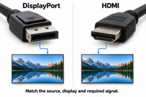
A resolution label alone is also incomplete. Record resolution, refresh rate, color format and any additional functions used. Compare those requirements with the exact cable model and length. Do not assume two products marked with a similar headline resolution will behave identically in your installation.
HDMI LA’s cable guidance explains certification and why cable length depends on construction.
Measure the route, not the gap between devices
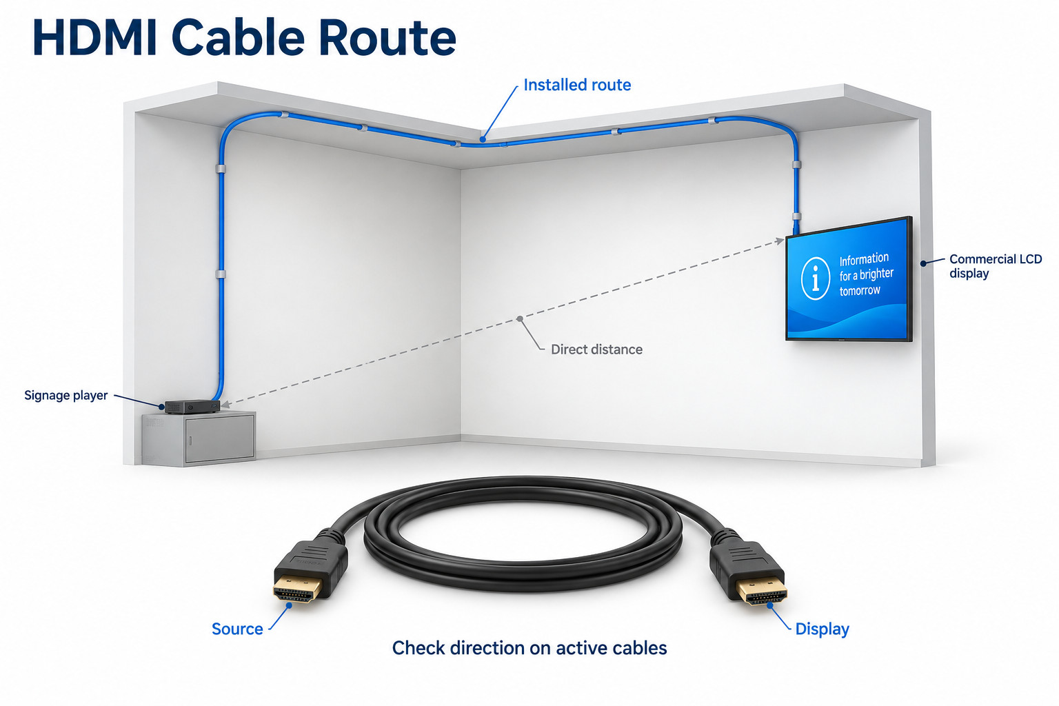
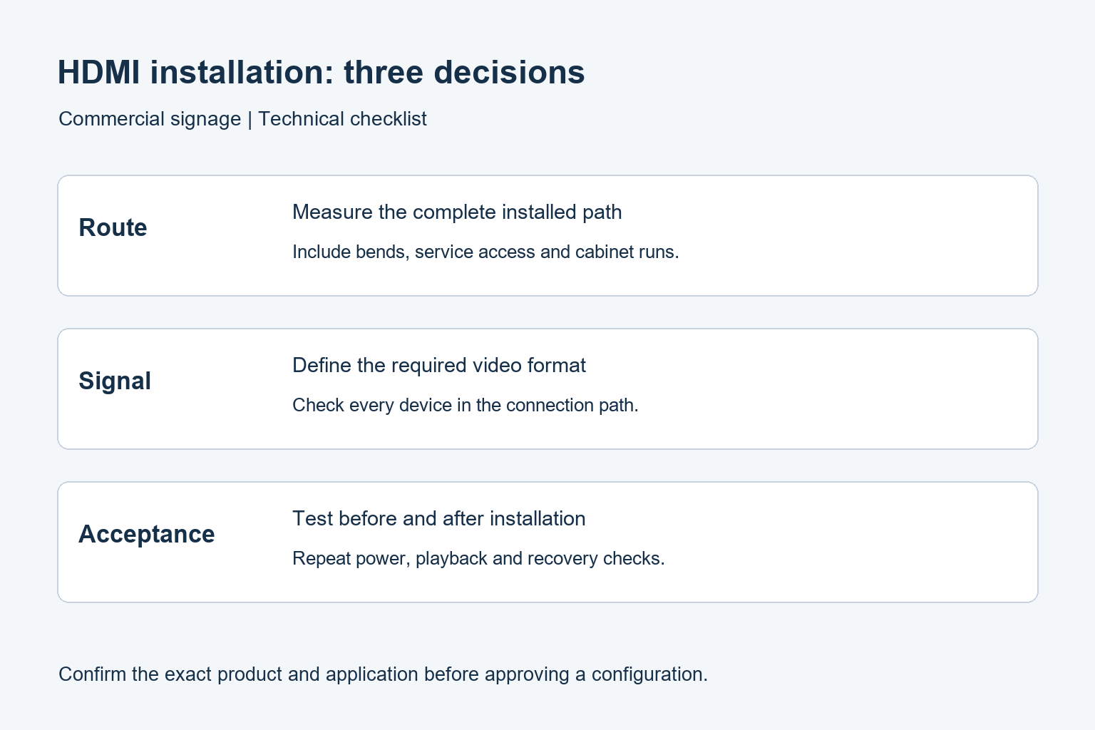
Trace the path from the source connector to the display connector. Include the cabinet, wall entry, ceiling route and final drop. Account for access needed to service the equipment. A straight-line measurement across the room can miss much of the installed run.
Mark every wall plate, coupler, adapter and intermediate device on the drawing. The installed path is a system, not just the longest cable. Keep the proposed layout with the quote so the supplier is evaluating the same connection that the installer will build.
Check connector clearance before buying a pre-terminated cable. A conduit may accommodate the cable body but not its plug. Follow the manufacturer’s pulling, bend and strain-relief instructions. Have the installation team confirm the route and access requirements before ordering, particularly for a concealed or difficult-to-replace run.
Choose the connection type against the project
Passive copper
A passive cable can be a straightforward choice for a suitable local connection. Confirm the specified signal at the required length and test the actual product. Avoid adding several adapters simply to make a marginal cable fit the route; include the complete arrangement in the acceptance test.
Active or optical HDMI cable
Active links contain electronics and can have directional installation requirements. Identify the source and display ends before pulling the cable. Confirm power requirements and any separate power connection. An inaccessible power adapter or reversed cable can turn a simple service task into a costly revisit.
HDMI Cable Power is a defined feature that requires support in both the cable and source device. A connector’s appearance does not prove this support. HDMI LA also explains the source-to-display direction of active cables. Use the instructions for the exact supplied assembly.
Read HDMI LA’s explanation of active cable direction and HDMI Cable Power.
A matched extender system
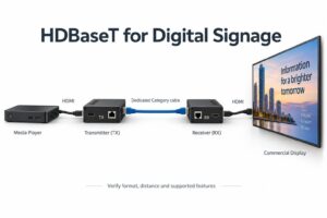
An extender may suit a route better than one long HDMI cable. Specify the transmitter, receiver, transport cable, power arrangements and supported signal as one system. Similar connectors do not establish compatibility between different manufacturers’ transmitter and receiver units.
Check whether control, audio return or other required functions pass through the proposed link. Do not infer support from video appearing on the screen. Keep these functions as separate lines in the test plan so the handover does not hide an incomplete feature behind a working picture.
Build a signal requirement sheet
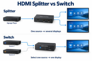
Record the player model, output configuration, display model and intended input. Include the longest route and any distribution or switching equipment. For installations with several branches, give each branch its own identifier and length rather than approving the system from the nearest display alone.
Keep the expected content with the requirement. Fine menu text, photographs and motion can reveal different concerns during commissioning. Test the final playlist at its normal settings, then investigate specific symptoms. Do not lower the signal quality silently just to make the demonstration appear stable.
Check color sampling requirements when the signage contains small text or detailed graphics.
Test before and after installation
First test the selected source, display and cable before the cable is installed. Use the intended settings and accessories. Label the tested components and save the result. This establishes a reference for investigating a problem that appears after the route is completed.
- Confirm a stable picture through a known working short connection.
- Test the proposed full-length link with its required power supply.
- Add the planned adapters, wall plates or intermediate devices.
- Run representative content at the agreed video settings.
- Check startup, standby and the normal reopening sequence.
- Repeat the checks after installation and document the final settings.
Choose a test period that represents the site’s operating pattern and agree on it in advance. A momentary picture is not the same as a completed acceptance test. Record dropouts, sparkles, unexpected resolution changes and recovery behavior instead of summarizing every intermittent issue as “no signal.”
When the short cable works but the installed route fails
Compare the two paths component by component. Check cable direction, required power and connector seating using the equipment instructions. Substitute one known working part at a time where access permits. Keep the original settings until the effect of each change has been observed.
If a simpler signal works, record that as a diagnostic result. It does not approve the original requirement. Review the specified capabilities of the complete path and ask the integrator to identify the limiting component before accepting a permanent change in resolution or color format.
A connection problem can also involve negotiation or content protection. Treat these as separate checks rather than assuming every failure is caused by length. Keep the source, display and intermediate-device details with any support request.
Use the HDCP troubleshooting guide when protected content is affected.
What to keep for maintenance
Label both ends with the destination and direction where relevant. Keep the cable model, length, route drawing, power-supply details and acceptance settings in the handover file. Record spare components that have actually been tested. A replacement described only as “another HDMI cable” may not reproduce the approved link.
Leave service access in the installation plan. Staff should be able to identify the player and required power connections without pulling on concealed cabling. Agree who handles a failed link and which observations the site team should collect before arranging a visit.
Review YJCEN commercial indoor displays for wall-mounted signage projects.