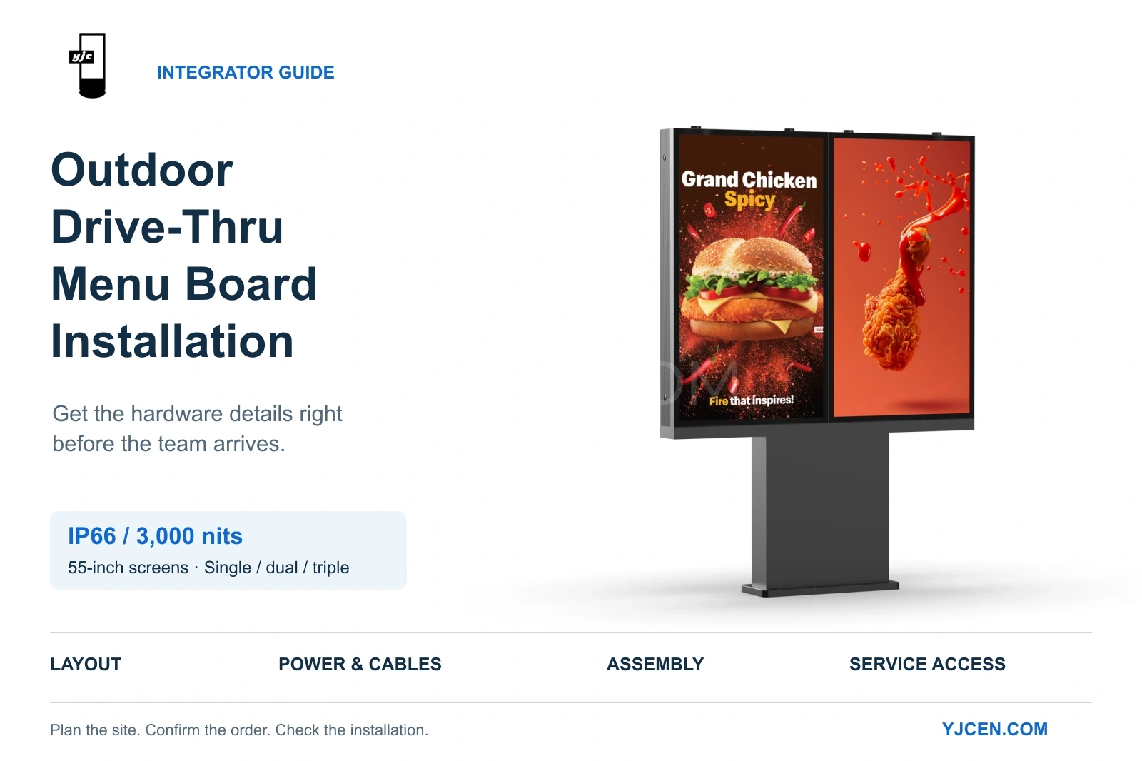
An outdoor drive-thru menu board installation starts before the equipment reaches the site. The integrator needs to confirm that the selected configuration fits the location, that power and cable routes match the equipment, and that the receiving party has arranged the required foundation and electrical work.
An IP66 protection rating and 3,000-nit brightness are important selection criteria. They do not, on their own, tell the installation team where to position the pedestal, how much power the complete configuration requires or how much space to leave for maintenance.
A useful installation checklist turns product specifications into confirmed drawings, connection requirements and clear responsibilities.
This guide uses YJCEN’s 55-inch digital drive-thru menu board as a practical example. It also includes two issues YJCEN has encountered during installation: unintended gaps caused by an incorrect assembly sequence, and screens that did not operate after installation because of wiring or supply problems.
Quick Guide: Key Hardware Checks for Drive-Thru Installation
Before scheduling the installation team:
- Confirm the equipment and layout. Match the screen count, outdoor specifications and dimensions to the order and site.
- Assign site responsibilities. Identify who will arrange foundation design, local wind-load and anchorage review, and electrical connection.
- Coordinate power and bottom cable entry. Check maximum power, cable routes and supplied cable lengths.
- Test each screen before assembly. Check the site supply, then confirm that each screen powers on individually.
- Follow the documented assembly sequence. Check alignment during installation and preserve rear access.
- Complete a working-system handover. Verify content placement, source selection, maintenance access and documentation.
1. Confirm the Outdoor Specifications and Screen Layout
Start by matching the product specification to the intended installation. Then use the applicable configuration drawing to coordinate the site.
The confirmed specifications for this YJCEN drive-thru menu board are:
| Item | Confirmed specification |
|---|---|
| Screen size | 55 inches per screen |
| Resolution | 3840 × 2160 pixels per screen, UHD |
| Brightness | 3,000 nits |
| Ingress protection | IP66 |
| Viewing angle, horizontal / vertical | 178° / 178° |
| Visibility with polarized sunglasses | Supported |
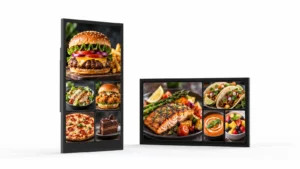
| Screen orientation | Portrait |
| Configurations | Single, dual and triple screen |
| Built-in system | Android 11 |
| External video input | HDMI IN |
| Automatic brightness control | Ambient-light sensor |
| Thermal management | Smart temperature control, smart fan control and overheating protection |
| Specified operating temperature | −45°C to +65°C |
Use the viewing specifications to plan the actual reading position
The display is specified with a 178° horizontal and 178° vertical viewing angle and supports viewing while wearing polarized sunglasses.
These features are relevant to drivers approaching a menu board from different positions. During layout planning, however, check the actual menu from the expected stopping point, including an off-centre position.
Screen height, orientation and text size still need to suit the site. A wide viewing-angle specification does not mean that small menu text will be equally easy to read from every angle or distance.
Include a viewing check with polarized sunglasses during commissioning, alongside checks for sunlight, reflections and any obstruction between the driver and the screen.
Check the complete configuration dimensions
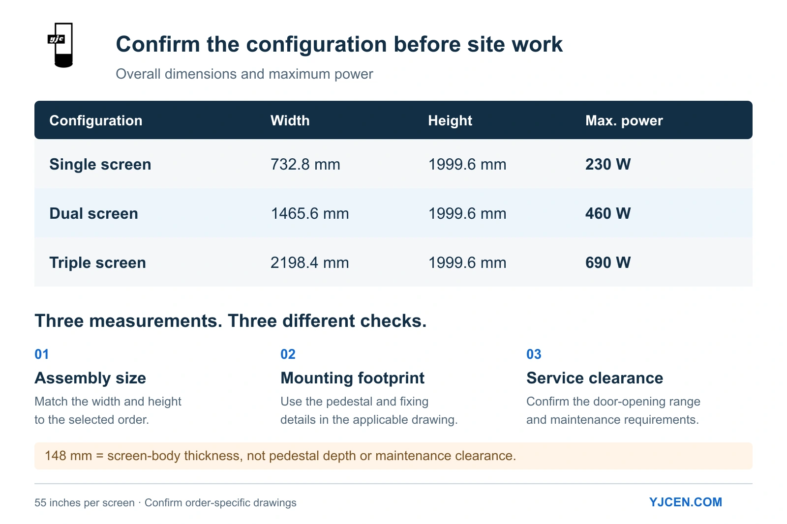
Adding screens creates more separate areas for menu content, but it also changes the assembly width and maximum power.
The current configuration drawings show:
| Configuration | Overall width | Overall height |
|---|---|---|
| Single screen | 732.8 mm | 1999.6 mm |
| Dual screen | 1465.6 mm | 1999.6 mm |
| Triple screen | 2198.4 mm | 1999.6 mm |
The existing drawings remain applicable to current shipments. Where an order includes customer-specific requirements, confirm the drawing that applies before coordinating site work.
Keep three measurements separate:
- Assembly dimensions: the overall width and height of the equipment.
- Mounting footprint: the pedestal and fixing positions.
- Maintenance clearance: the space needed to open the rear doors and carry out service work.
The documented 148 mm dimension is the screen-body thickness. It is not the complete pedestal depth or a rear-clearance requirement.
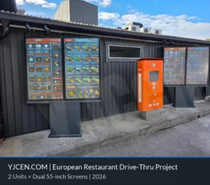
For a deployed multi-screen layout, see our European dual-screen drive-thru menu board project. The project used two units, each containing two 55-inch portrait displays. Use it as a layout reference while confirming dimensions and mounting details against your own order drawings.

2. Coordinate IP66 Protection With the Intended Cable-Entry Arrangement
IP66 is the confirmed protection rating of the display. The installation plan should also preserve the equipment’s intended enclosure and connection arrangement.
Power, network and HDMI cables enter this product from the bottom. Coordinate the entry position with the pedestal and fixing layout before the equipment is secured.
Confirm:
- Where the site cables will arrive beneath the pedestal.
- Whether that position matches the applicable drawing.
- Whether the proposed cable route conflicts with fixing positions.
- Whether any requested change to the entry point or enclosure needs manufacturer confirmation.
Do not treat an IP66 equipment rating as permission to add openings or change the cable-entry arrangement without review. If the project requires a modification, confirm the proposed arrangement with the manufacturer before installation.
Compare supplied cable lengths with the planned route
| Supplied cable | Confirmed length |
|---|---|
| Power cable | 1.5 m |
| Network cable | 1.5 m |
| HDMI cable | 1.5 m |
These figures describe the supplied cable lengths. They do not mean that 1.5 m will remain available outside the pedestal after routing.
Check the actual connection positions and confirm cable quantities against the specific order. A marked cable-entry location and connection plan are more useful to the installation team than a general note stating that power is available nearby.
3. Verify the Order-Specific Mounting Hardware and Site Responsibilities
Pedestals, brackets and anchor lists can differ between single-, dual- and triple-screen configurations. Customer requirements can also affect what is supplied.
Use the specific order’s drawings and packing list rather than assuming that one accessory list applies to every installation.
The current installation manual illustrates a dual-screen assembly. It explains the sequence, but its component quantities should not be treated as a universal packing standard.
Before dispatch, confirm:
- The pedestal and support arrangement.
- The types and quantities of supplied brackets, fasteners and anchors.
- Any components the recipient must provide locally.
- The drawings and installation instructions the site team will use.
- Whether custom requirements affect mounting or assembly.
Make the recipient’s site responsibilities explicit
For the supply arrangement described here, the recipient is responsible for arranging the following work:
| Work | Responsibility to confirm |
|---|---|
| Foundation design and construction | Who will design and prepare the foundation for the actual site |
| Local wind-load and anchorage review | Who will review the fixing arrangement against local conditions |
| On-site electrical connection | Who will prepare and connect the site supply |
If the integrator is coordinating the project for an end customer, assign these tasks to specific responsible parties.
A supplied anchor list identifies the components included. It does not, by itself, establish that the foundation and anchorage have been reviewed for the project site.
4. Use the Correct Maximum Power for the Selected Configuration
The confirmed maximum power is 230 W per screen.
| Configuration | Maximum power |
|---|---|
| Single screen | 230 W |
| Dual screen | 460 W |
| Triple screen | 690 W |
The 460 W figure in the documentation refers to the dual-screen configuration. It is neither the single-screen figure nor a maximum that applies to every configuration.
The equipment uses a unified incoming power supply. The documented input is AC 100–240 V, 50/60 Hz.
Provide the selected configuration, maximum power and relevant equipment documentation to the party responsible for the site electrical connection. These figures describe maximum power, not average energy consumption during daily operation.
If the project changes from two screens to three, update the quotation, layout dimensions, power information and applicable order documents together.
5. Check Site Power and Test Each Screen Before Assembly
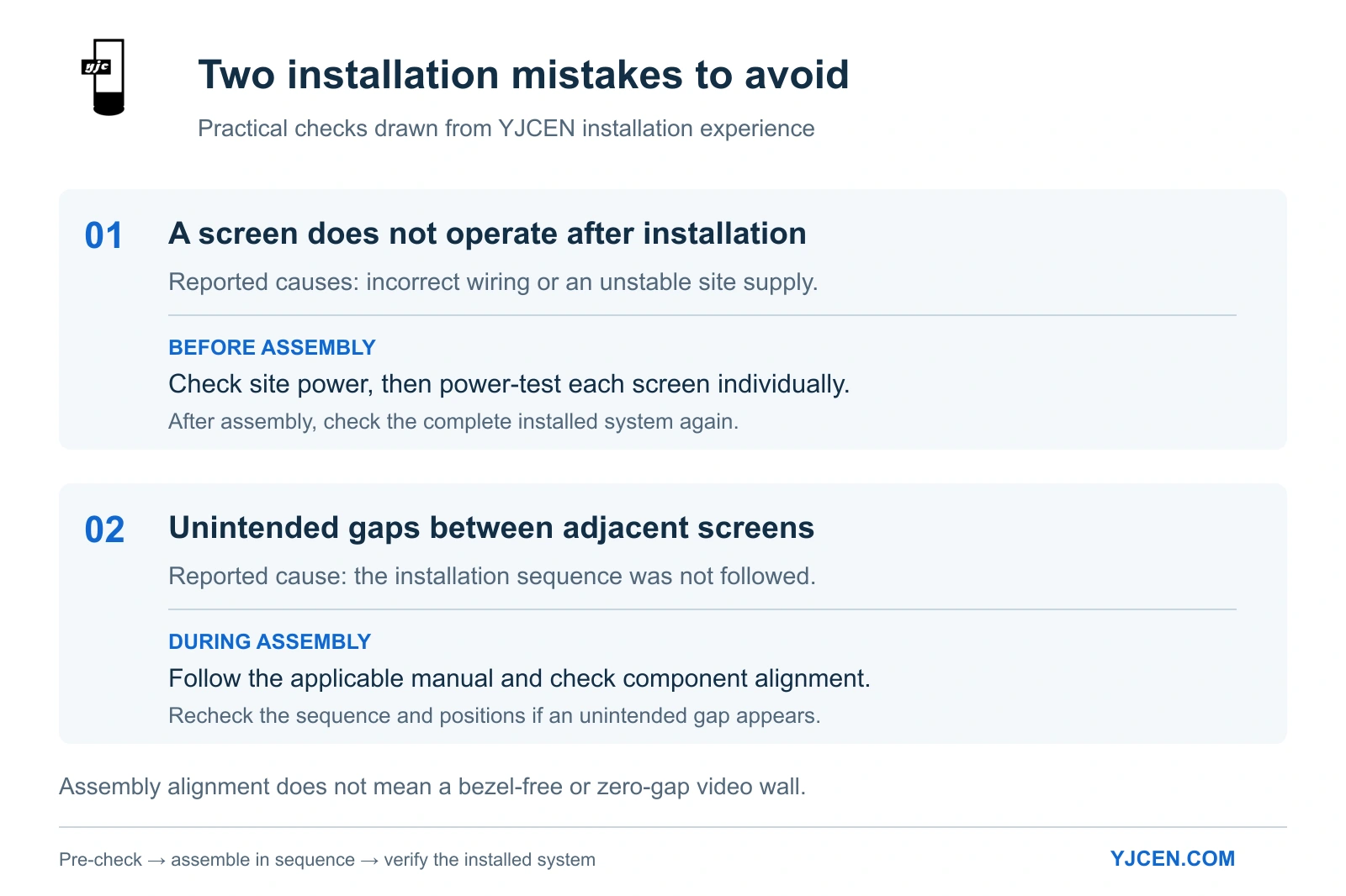
YJCEN has encountered screens that did not operate after installation because of incorrect wiring or an unstable site supply.
The practical lesson is to establish an initial operating check before the screens become part of the complete assembly.
Step 1: Check the site supply
Before installation, have the party responsible for the electrical work check that the site supply is stable and suitable for the equipment.
Step 2: Power-test each screen individually
Before final assembly, power-test each screen to confirm that it turns on and the display lights up.
Record which screens have been checked so that the results can be matched to their final installation positions.
Step 3: Test the installed system
After assembly and connection, check that all screens operate with the site connections and intended content source.
| Check | What it establishes |
|---|---|
| Individual screen test before assembly | Each screen powers on before installation |
| Installed-system test | The completed installation operates with the site connections and intended content source |
If a screen does not operate after installation, the earlier result provides a useful reference for troubleshooting. Wiring and supply conditions are points to investigate, but they are not the only possible causes.
Do not leave the first power-on check until the complete installation is finished.
6. Follow the Assembly Sequence to Avoid Unintended Screen Gaps
Another issue reported by YJCEN is the appearance of unintended gaps between adjacent screens.
One cause encountered in practice was an incorrect assembly sequence: the equipment had not been installed in the order specified by the instructions.
To reduce this risk:
- Review the instructions applicable to the order before starting.
- Follow the specified sequence for the pedestal, supports, frames and screens.
- Check component positions and screen alignment against the drawing during assembly.
- If an unintended gap appears, recheck the sequence and component positions before continuing.
This is a check for gaps caused by incorrect assembly. It is not a claim that the product forms a bezel-free or zero-gap video wall.
Correctly specified equipment still needs to be assembled correctly. Following the documented sequence is part of achieving the intended mechanical arrangement.
7. Confirm the Content Source and Screen Positions
The documented configuration includes a built-in Android 11 system and an HDMI input for an external source.
Connecting an external source to HDMI IN automatically switches the screen to that source. The remote control can also be used to switch inputs.
Before commissioning, agree on the intended operation:
| Operating arrangement | What to check |
|---|---|
| Built-in Android system | The intended content is ready and displays correctly |
| External HDMI source | The customer’s source equipment is available for an actual playback check |
| Input switching | The recipient understands how to select the required source with the remote control |
Typical dual- and triple-screen menu boards show different content on each screen, such as menu categories, meal deals or promotional information.
Prepare a simple content-position list. Define left, centre and right from the customer’s viewing position, so that the content and installation teams use the same reference.
During acceptance, confirm that the correct content appears on each screen. Review the menu from the intended driver position, including prices, product names and other information needed to place an order.
8. Preserve Maintenance Access and Complete the Handover
Equipment that fits into its assigned position may still be difficult to service.
There is no universal rear-clearance value for every order. Confirm the required space against the door-opening range and maintenance requirements of the specific order.
Before fixing the equipment in its final position, check whether walls, fencing, landscaping or nearby equipment could obstruct the rear doors or required service work.
Complete the installation with an order-specific handover record:
| Handover item | What to verify |
|---|---|
| Product configuration | Screen count, dimensions and confirmed specifications match the order |
| Supplied components | Pedestal, brackets and accessories match the packing list |
| Site work | The recipient’s responsible parties have confirmed completion of foundation and electrical work |
| Assembly | The equipment matches the applicable drawing and alignment has been checked |
| System operation | All screens turn on and display correctly |
| Content and viewing | Content is in the correct position and essential menu information is readable from the intended driver position |
| Source selection | The intended source operates and the recipient understands input switching |
| Maintenance access | Rear doors and required service areas remain accessible |
| Documentation | Drawings, instructions and support contact details are available |
Record any outstanding items, the responsible party and the agreed follow-up.
Frequently Asked Questions
Are IP66 protection and 3,000-nit brightness enough to determine the installation plan?
No. They are important product specifications, but the plan must also address configuration dimensions, site positioning, foundation requirements, power, bottom cable entry and maintenance access.
Can the display be viewed while wearing polarized sunglasses?
Yes. The product documentation specifies visibility with polarized sunglasses. Include a check from the intended driver viewing position during commissioning to assess the actual menu, screen position and site conditions.
Does the 178° viewing angle eliminate the need to check the screen position?
No. The specified viewing angle is 178° horizontally and vertically, but menu readability also depends on viewing distance, text size, screen position and site conditions.
Does the 148 mm dimension describe the complete pedestal depth?
No. It describes the screen-body thickness. Refer to the applicable drawing for pedestal and fixing details.
Which configuration does the 460 W figure refer to?
It refers to the dual-screen configuration. Maximum power is 230 W for a single screen, 460 W for dual screens and 690 W for triple screens.
Are the mounting accessories identical for every configuration?
No. Pedestals, brackets and anchors vary with the configuration and customer requirements. Use the packing list and drawings for the specific order.
What should be checked if unintended gaps appear between screens?
Check the applicable instructions, assembly sequence and component positions. YJCEN has encountered gaps caused by installing multi-screen assemblies in the wrong order.
Why test each screen before assembly?
An individual power-on check establishes that each screen lights up before installation. The completed system still needs to be tested afterward to verify operation with the site connections and intended content source.
How much maintenance space is needed behind the equipment?
There is no universal value. Confirm the required clearance against the door-opening range and maintenance requirements of the specific order.
Preparing a Drive-Thru Menu Board Installation?
Send YJCEN your proposed screen count, site layout, installation location and intended content source. Include the planned bottom cable-entry position and any mounting requirements.
We can help confirm the equipment configuration, applicable drawings and supplied components, and prepare a quotation based on your project requirements.