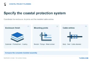
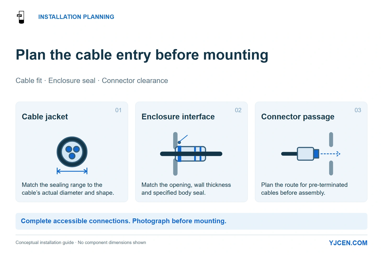
Plan three interfaces: the cable jacket, the entry-to-enclosure seal and the connector’s passage through the opening. Complete accessible connections and photograph them before mounting conceals them.
To preserve an outdoor display’s IP protection, match each field-installed cable entry to the cable jacket, enclosure interface and specified sealing arrangement. With YJCEN IP66 Outdoor Digital Signage, distinguish the supplied display connections from entries added by the installation team. Assign responsibility for those entries before ordering, complete the connections while they remain accessible, and record the finished arrangement before the display or surrounding structure conceals it.
The useful handover question is: does every cable crossing the enclosure boundary retain the specified seal in its final installed position? A gland label, a tidy cable route and a working screen each tell only part of that story.
1. Where Does the Display’s IP Protection Need to Continue?
Mark the protected enclosure boundary on the installation drawing. Identify where each cable crosses it, which connections arrive assembled, and which entries the installer will complete on site.
YJCEN’s test report BKC23114331KS records passing IP6X and IPX6 results for model YJC-550-OD09-A. Preserve the specified connection arrangement during installation, and apply the project’s required IP protection separately to any added junction box, entry plate or other enclosure in the route.
A cable gland is one way of sealing an entry. Where the selected configuration uses a factory-sealed cable, a sealing connector or another specified entry system, retain that arrangement rather than adding an unnecessary gland or drilling a new opening.
For an installer-fitted gland, trace two interfaces: the seal around the cable jacket and the seal between the gland and the enclosure. A cable can be firmly gripped while the enclosure-side seal is missing or incorrectly seated.
2. What Must Fit: The Cable, Connector or Mounting Hole?
Start with the cable jacket that the seal will contact
Select the gland’s sealing range from the actual cable outside diameter and shape. The thread designation describes the mounting interface; it does not, by itself, identify the cable sizes that the insert will seal.
LAPP’s cable-gland guidance distinguishes the cable clamping range from the connection thread and describes sealing at both the cable and housing interfaces. Record the selected part’s range beside the cable specification so a later cable substitution triggers a fit check.
| Interface | Selection decision | Installation consequence |
|---|---|---|
| Cable jacket and sealing insert | Match the actual outside diameter, shape and number of cables to the insert | The insert closes around the intended jacket geometry. |
| Gland and enclosure | Match the thread or clearance-hole arrangement, wall thickness and specified enclosure-side seal | The gland can seat correctly and be secured as designed. |
| Connector and assembly route | Decide whether the cable is terminated before or after passing through the entry | A large connector does not force an oversized seal around a smaller cable. |
YJCEN’s IP66 range includes HDMI input and Ethernet RJ45 connectivity. For a connection routed through a field-installed entry, record whether the selected cable arrives with its connector already fitted; the connector head and the cable jacket present different fit problems.
If a pre-terminated connector cannot pass through the planned entry, select a compatible connectorized feedthrough, split entry or revised assembly sequence before cutting the enclosure. Icotek’s connectorized-cable entry systems illustrate how split sealing elements accommodate pre-terminated cables; the chosen system still needs to fit the display’s approved entry arrangement.
Give unused entries a finished configuration
Close unused openings with the specified blanking component and its required seal. For a multi-cable insert, use the designated closure for each unused position; for a single-cable gland, follow that part’s unused-entry arrangement.
Include those closures in the order quantities. This avoids a completed electrical installation waiting for small sealing parts that were omitted from the purchasing list.
3. Who Supplies and Installs Each Part of the Entry?
Divide responsibility at the actual connection point. “Display supplied” and “cabling by others” leave too much ambiguity if neither package names the glands, seals and unused-entry closures.
| Work item | Allocate it before the order | Deliverable |
|---|---|---|
| Display connection arrangement | Display supplier and integrator agree the selected configuration | Connection detail showing what arrives fitted and what remains for site work. |
| Field cables and entry components | Name the party supplying each cable, gland, seal, adapter and closure | Cable-and-entry schedule with quantities and compatible part references. |
| Site assembly | Name the installer completing the entries and cable support | Installation completed to the selected component instructions. |
| Handover and later changes | Name the party recording completion and maintaining the entry schedule | Photographs, assembly records and an updated record after cable replacement. |
For a freestanding installation, coordinate the base opening and site cable route before civil work fixes the conduit position. The conduit must lead to the intended entry without forcing the cable against a sharp edge or sideways through its seal.
Close these scope items with the outdoor LCD buying checklist before comparing final prices. Count the entry components and installation labor in the same quotation as the cables they serve.
4. When Should the Installer Check and Photograph the Entries?
Complete the accessible connection work before mounting conceals it. Step 9 of YJCEN’s Outdoor IP66 Display installation manual places electrical cable connection before lifting the display onto the wall mount.
For that wall-mounted arrangement, make entry inspection and photography part of the same pre-mount stage. It is easier to correct a misplaced seal or unsuitable cable route while the connection area is reachable than after the display is fixed against the wall.
Use this sequence for the site work that applies to the selected configuration:
- Identify the supplied arrangement. Match the planned cables and entry components to their assigned positions before assembly.
- Complete the entries with the supply isolated. Seat the specified seals and closures, then secure the assembly using the selected component’s installation method.
- Support and route the cables. Provide the cable’s required bend radius and enough access for connection or service without pulling sideways on the seal.
- Capture the accessible details. Photograph each completed entry and its location before mounting or closing the surrounding structure.
- Check the final position. After mounting, establish that the route has not pinched the cable, loosened a connection or displaced a seal; then complete the planned functional commissioning.
Use the tightening sequence and torque requirements for the actual component, including separate body and cap-nut instructions where applicable. CMP’s installation guidance stresses that gland types are not all installed in the same way; “tighten until it feels secure” is a poor substitute for the selected part’s instructions.
Keep four views in the handover record: the overall route, the enclosure-side interface, the cable-side seal, and the unused-entry closures. Associate the images with the display identifier and cable schedule; record specified tightening separately because a photograph cannot show the applied torque.
These records document assembly and access. If the project requires an ingress test, agree its method, acceptance criteria and responsible test party in advance rather than improvising a hose test at handover.
5. Which Installation Errors Need Correction Before Handover?
| Finding | Why it matters | Corrective action |
|---|---|---|
| Cable outside the selected insert’s range | The gland can fit the enclosure while the cable seal is unsuitable | Change to the specified compatible insert, gland or cable combination. |
| Several cables placed in one single-cable seal | The seal geometry does not match the cable bundle | Use a designed multi-cable entry or separate entries in the approved layout. |
| Cable has been changed after entry selection | The replacement jacket may differ in diameter or shape | Recheck the replacement against the entry specification before reconnecting. |
| Enclosure-side seal is missing, damaged or trapped | Tightening the cable-side nut does not repair that interface | Reassemble with the specified sealing parts and correct seating. |
| Unused opening or unfilled insert position remains | The protective boundary contains an unfinished path | Fit the designated closure before completing the installation. |
| Cable is pulled sideways or pinched after mounting | The final position changes the load on the seal or damages the jacket | Correct the routing and support, then reinspect the affected entry. |
Photograph the corrected assembly and update its entry record. If a cable is replaced later, repeat the checks affected by that change rather than treating the original handover as permanent evidence for a different cable.
6. Copyable RFQ and Cable-Entry Handover Fields
Send the entry schedule with the mounting drawing. The first block defines the parts and responsibilities to price; the second records what was actually installed.
RFQ fields
Handover fields
7. Outdoor Display Cable-Gland FAQ
Does a gland with an IP66 marking make every installation IP66?
No. The cable, enclosure interface, seals and assembly must match the requirements for the selected entry system.
Does every outdoor display connection need an installer-fitted cable gland?
No. Retain the selected factory connection system and specify glands where the site-installed entry design requires them.
Can the thread size alone determine which cable will seal?
No. Match the actual cable jacket to the selected insert’s sealing range and shape.
Can a pre-terminated HDMI or Ethernet cable use a split entry?
Yes, where the selected split system suits the cable and approved enclosure interface. Include the connector dimensions and cable jacket size when choosing the arrangement.
Should cable entries be photographed before wall mounting?
Yes, when mounting will restrict access to the connection area. Photograph the completed entries before mounting and check that the final position preserves the arrangement.
Is a photograph enough to prove an IP test result?
No. Use photographs for installation records and the specified test report for any required ingress-test result.
Send Your Cable Schedule and Mounting Drawing
Send the selected display model, cable schedule, connector dimensions and mounting drawing for custom display configuration and mechanical-fit coordination. Identify the connections supplied with the display and the site-installed work so the entry components, assembly sequence and installation responsibilities can be settled in the quotation.